
Hitch Step Bike Rack
CAD | FEA | DFM
Designed a multifunctional bike rack that doubles as a hitch step. The rack features fold-out ramps that allow bikes to be rolled onto the rack rather than lifted. Using welded steel tubing and simple mechanisms, the design balances ease of use, safety, and manufacturability. Structural analysis and CAD modeling were used to ensure strength and stability under realistic loads.
Step 1: Outline the Project
1.1 Problem Statement
Current bike rack designs pose major challenges, including cumbersome installation, restricting trunk access, and requiring the lifting of awkward, heavy bikes. My project proposes a conceptual alternative bike transport design that minimizes lifting and reduces bulk without limiting any vehicle functions, making biking more accessible and convenient.
Few of the many bike rack options in the market truly reduce lifting effort while maintaining car functionality. Existing ramp racks still require bending and lifting and block trunk access, while motorized systems are heavy, costly, and impractical. This concept builds on these designs, presenting a less bulky, more practical, and cost-conscious approach to assistive bike transport.
1.2 Standards and Codes
The following tables outline the standards and codes that guide the bike rack design, ensuring the concept meets user needs, safety requirements, and industry standards.


Step 2: Design a Solution
2.1 Conceptual Designs
2.2 Decision Matrices for Design Selection
Pugh’s Method, Pahl and Beitz Method (Weighted) & Pahl and Beitz State Space Plot (Technical vs. Economic Plot)
Hinged Ramp Rack emerged as the best option, offering a balanced combination of affordability, usability, and vehicle integration while maintaining structural stability and durability


2.3 Design Description
The hinged ramp bike rack is built primarily from A36 steel, chosen for its weldability, strength, and cost-effectiveness. The design centers around the primary subassembly, a welded hitch insert assembly that includes the hitch insert, gussets, crossbars, center deck, end caps, and wheel guides. All components in this subassembly are fully welded to ensure structural integrity and long-term durability under dynamic loading conditions.
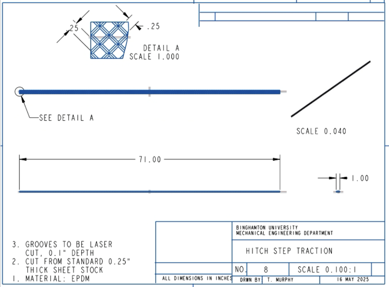
The complete assembly incorporates folding ramp arms, attached using hex bolts and nylon lock nuts to provide reliable, low-maintenance hinges. When closed, the ramp surface doubles as a hitch step, featuring EPDM rubber tread bonded with 3M 5200 Marine Adhesive for permanent adhesion, slip resistance, and weather durability.


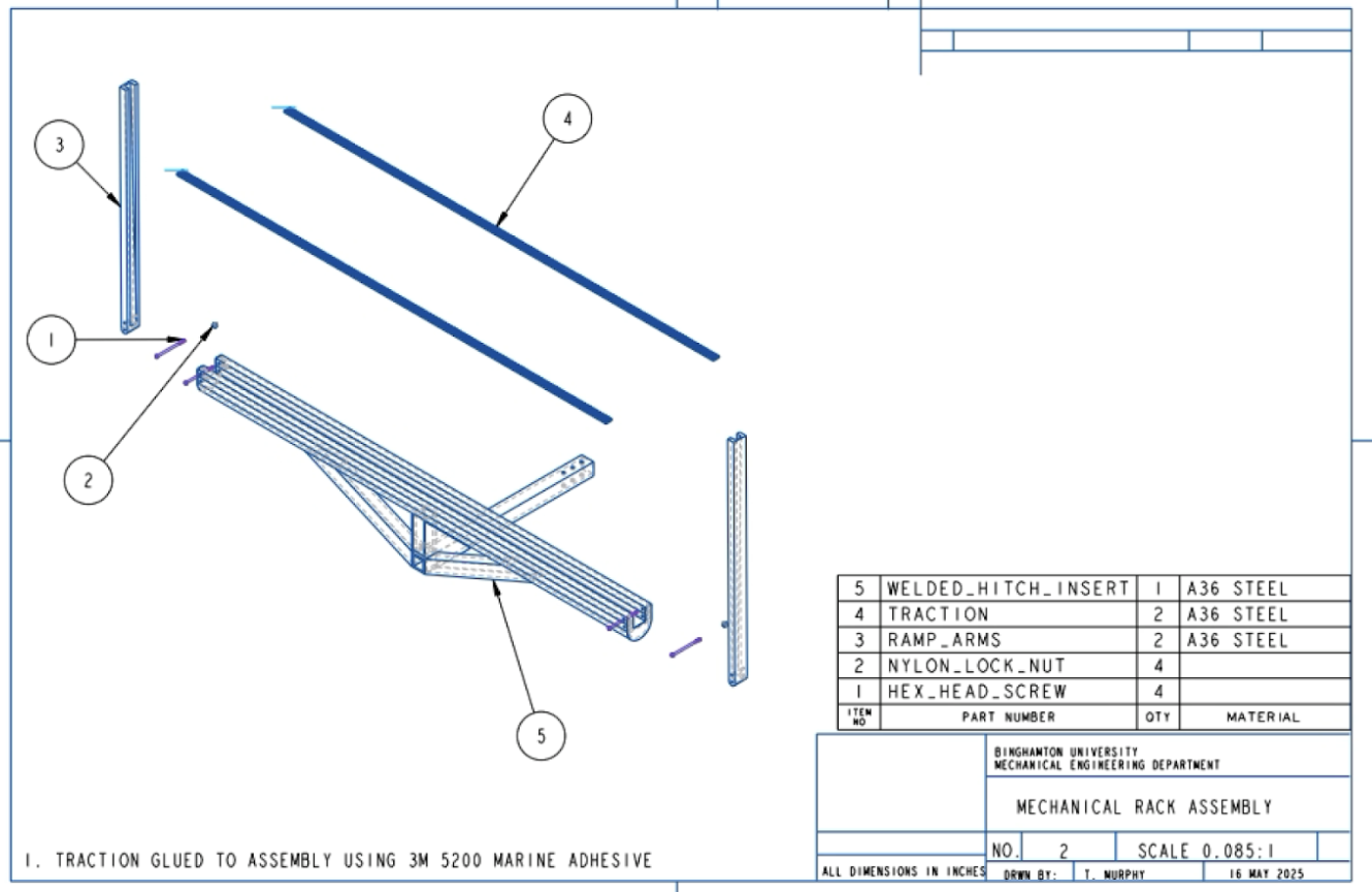
When folded, the ramp functions as a hitch step, similar to products offered by WeatherTech, allowing users to easily reach the roof of the vehicle for maintenance or securing items. This dual functionality ensures that the bike rack can remain mounted even when not in use, maintaining full vehicle accessibility while providing the added convenience of a step integrated into the rack.

2.4 Manufacturing of Parts
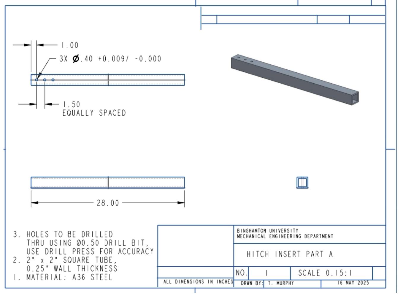
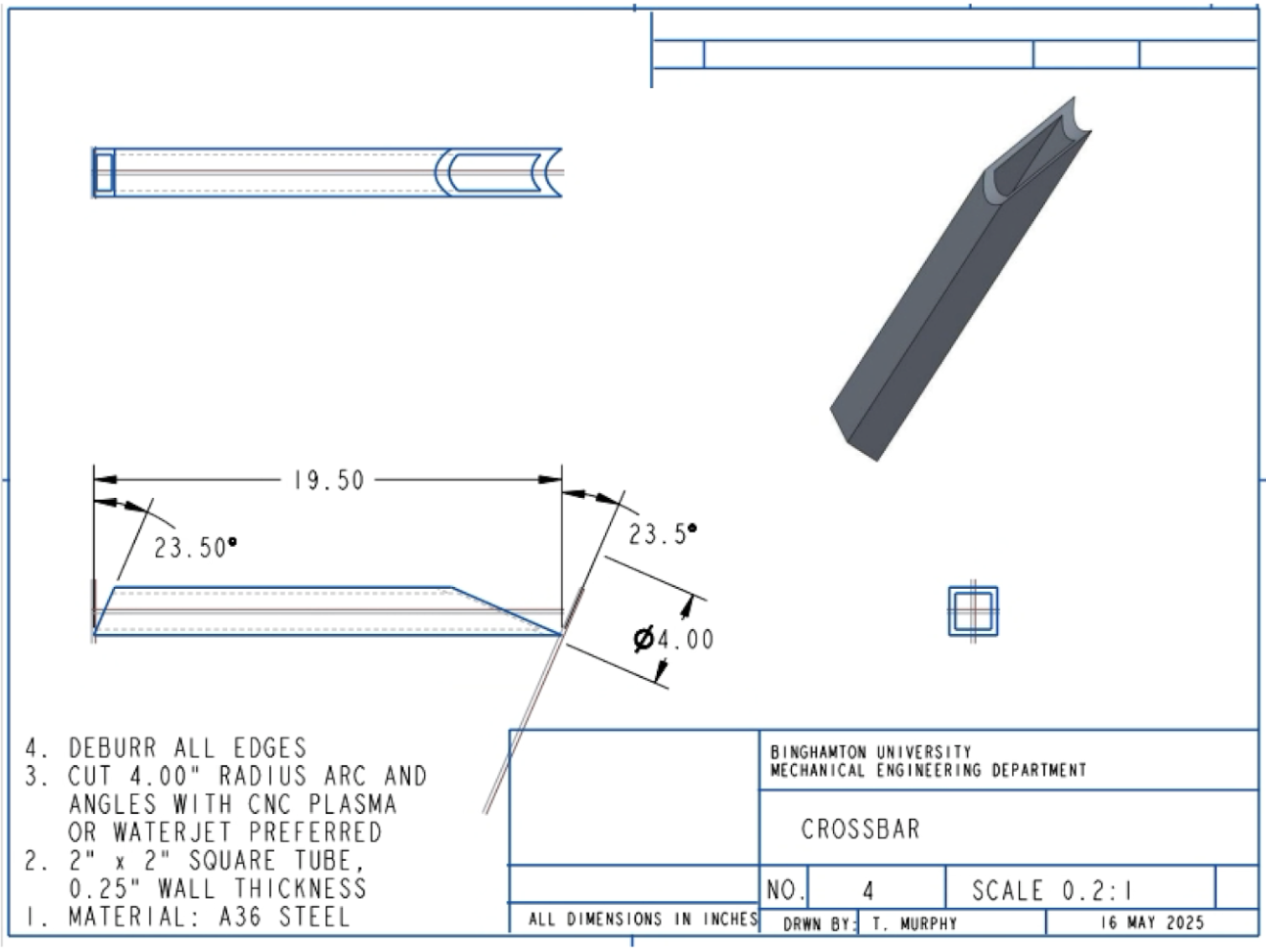
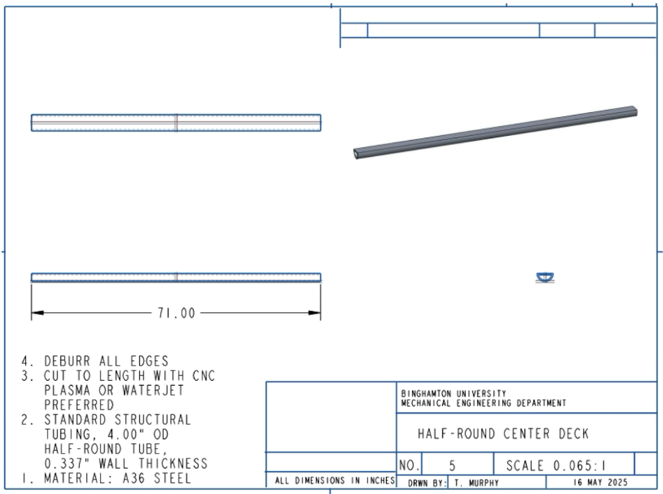
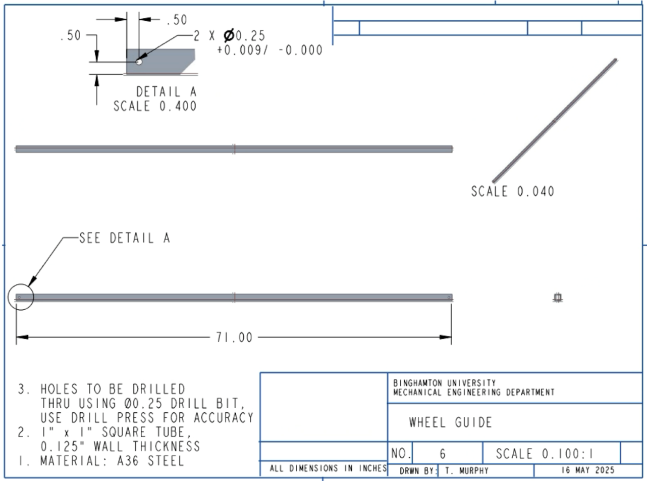
The design prioritizes ease of fabrication and cost efficiency through the use of standard steel stock and straightforward shop processes. The main hitch insert is made from 2x2-inch A36 steel square tubing reinforced with sheet steel gussets for added strength and stability during welding. The half-round steel center deck, serving as the primary load-bearing member, is welded directly to the hitch insert, with its wall thickness optimized in MATLAB to balance weight and stiffness. Crossbars made from 2x2-inch tubing are welded across the assembly to reduce bending moments, while 1x1-inch wheel guides are welded to the flat top of the center deck to secure the bike tires.
End caps are cut from sheet steel and welded to close the tubing, preventing corrosion and giving the assembly a finished appearance. All primary components are fabricated from standard stock using saw cutting or CNC plasma cutting for precision and repeatability, then joined using MIG welding for consistent, high-strength joints. The ramp arms are CNC-machined for accurate hinge alignment and attached with hex bolts and nylon lock nuts for easy installation and maintenance. EPDM rubber tread is bonded to the ramp surface with 3M 5200 Marine Adhesive, providing a permanent, weatherproof grip.
By minimizing the number of unique parts, standardizing tube dimensions, and using off-the-shelf fasteners, the design achieves efficient fabrication, reliable assembly, and long-term durability suitable for small-scale or commercial production.


Step 3: Perform Engineering Analysis
3.1 Finite Element Analysis
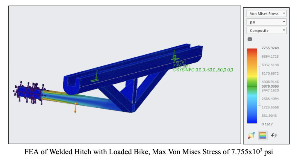
Von Mises stress was used as the failure criterion to predict yielding in A36 steel, ensuring the design remains durable during both static and dynamic loading. Three loading cases were analyzed on the welded hitch insert and center deck assembly, which acts as the primary load-bearing structure:
Bike Loading: Simulates a bike being rolled onto the rack. The weight was applied at the wheel contact points on the ramp side. The maximum Von Mises stress was 7,755.9 psi, resulting in a Factor of Safety (FOS) of 4.64.
Bike Loaded: Represents the static condition of the bike fully supported by the center deck. The stresses concentrated at the welds between the deck and crossbars remained well below the yield strength of A36 steel.
Human Loaded: Models a person stepping on the closed ramp while the rack functions as a hitch step. The applied load produced a maximum stress of 19,430 psi, corresponding to a FOS of 1.85, confirming safe performance under human use.


Additional analysis was performed on the ramp hinge connection, where each arm pivots on a Grade 8 steel hex bolt (¼"-28 thread, 4½" long) with a nylon lock nut. During bike loading, the hinge experienced a downward force of 8.33 lbf and a horizontal force of 44.98 lbf, resulting in a maximum stress of 7,766 psi and a FOS of 4.63.
The pin connection of the ramp arm recorded a maximum Von Mises stress of 2,321.5 psi, yielding a FOS of 15.5, indicating high strength and minimal risk of failure.
3.2 Computational Fluid Dynamics
CFD was used to assess the aerodynamic impact of the bike rack. Three scenarios were analyzed: car alone, car with unloaded rack, and car with loaded rack. The rack remains within the vehicle’s rear profile, and maximum flow velocities were nearly identical (46.17–46.19 m/s), indicating minimal effect on drag.

Final Design
