Fixture Design
Creo | 3D Printing | Prototyping
Fixtures were modeled to support the Astronics Safety and Emergency manufacturing line, which produces flashlights, emergency transmitters, and first-aid kits. New fixtures were created to improve workflow efficiency and support new product assemblies, while existing ones were redesigned for better usability. Each design emphasized simplicity, durability, and seamless integration into current manufacturing operations.
Wire Bend and Tinning Fixture
To assemble the battery pack as shown, the wires need to be bent at a specific height to reach their connection points. This fixture holds the connector and wires in place, with its top edge marking where the wires should be bent 90° and tinned before being attached to the top of the battery.


Soldering Mount
This mount was designed for a different battery pack with solder joints at both the top and bottom. Previously, the pack was held in foam, which was not a reliable solution. The new angled fixture positions the pack toward the solderer and can be flipped for access to both soldering points.


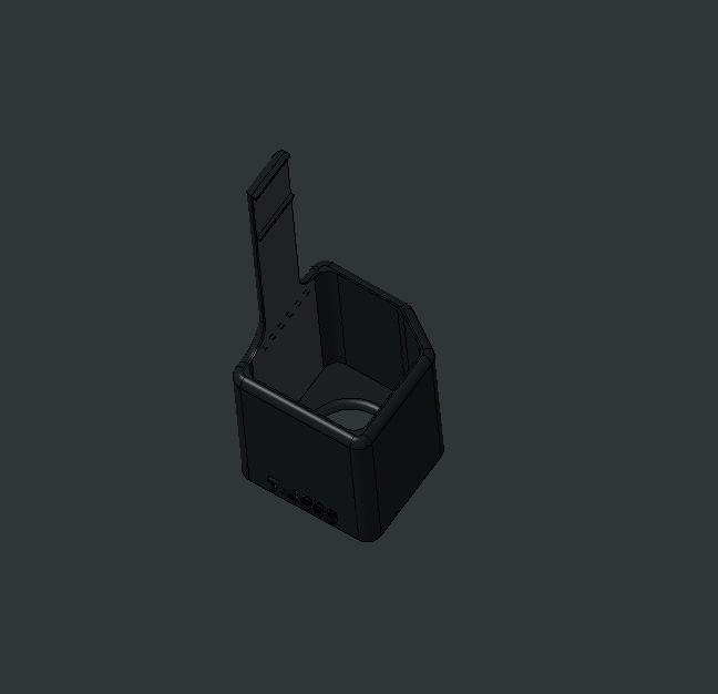
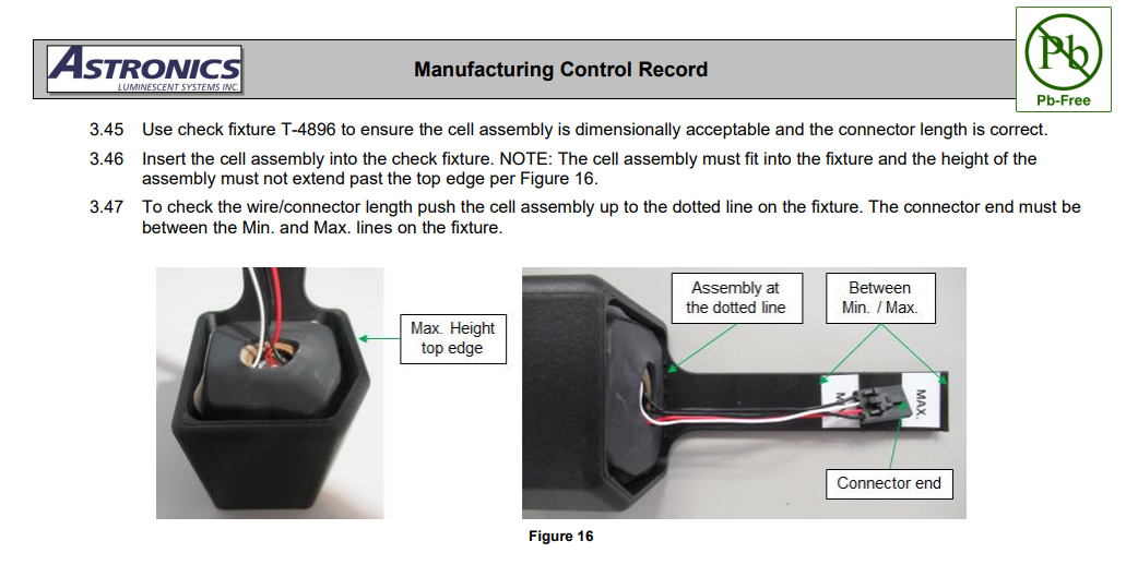
Dimension Verification Tool
This fixture was designed to verify the battery pack’s height, width, and connector wire length. It features a unique fit that ensures correct orientation, minimum and maximum wire length markings, and a base hole for easy removal after measurement. Below are the usage instructions from the manufacturing control report.


Redesigns
Several legacy fixtures were hand-built and difficult to reproduce as production scaled. By redesigning them for 3D printing, they became easily replicable, shareable across facilities, and quick to produce on demand.
Free-Standing Soldering Fixture
This fixture went through several design iterations before concluding that the most efficient solution was a streamlined 3D-printed version of the original. Input from the operators was invaluable during development. The freestanding design lets the solderer align the battery connections freely, without fitting the pack into a fixed slot. The black and red markings, labeled “B” and “R,” indicate where to solder the male connector to the battery wires.


Training Soldering Set-Up
This fixture was designed to train new solderers on connecting the battery to the male connector. The horizontal orientation helps stabilize the battery, though it requires an extra step to properly align it. Small triangular features hold one wire aside while the other is soldered, which is an upgrade to the screws used in the original fixture. The “B” and “R” markings again indicate where each wire connects to the male connector.


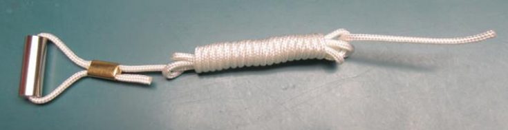
Lanyard Tying Fixture
This lanyard, used for an emergency transmitter, was originally tied by looping it around the operator’s fingers without any fixture. A prototype fixture was later developed and then refined into the 3D-printed version shown. The new design significantly reduced hand strain by allowing the pegs to hold the loops instead.